Lastest version of this article | More articles
|
|
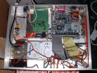
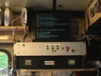
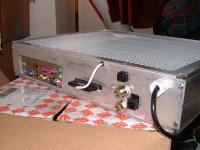
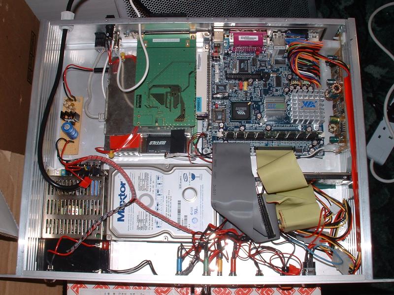
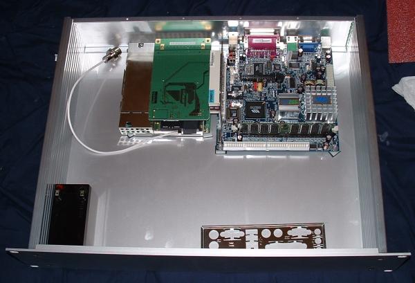
| Completed unit with top cover removed (enlarge) | 2U rack box used as satellite router (enlarge) |
Our intention was to produce a 19 inch rack mountable box containing a fully functional computer along with a wireless bridge. Having battled with cardboard boxes of equipment whilst implementing various wireless network topologies, the time had come to make a flexible device capable of many of the more common configurations that we have used over the last year or so. In previous installations, we had employed a laptop as a router and firewall along with various proxy software to accelerate web browsing and DNS caching. In addition to this machine, we have been using a multitude of 802.11b bridges, routers and extended range antennas.
In production environments, such as festivals and other outdoor events, several issues often arise that do not pertain to the network configuration; such as power distribution 'going up and down like a yoyo', people accidentally pressing buttons on equipment that they know nothing about and the octopus/spaghetti effect of introducing so called 'wireless' network equipment into the loop. With these issues in mind, we chose to build a box that would be bullet-proof in such an environment.
The main components of the box are as follows:

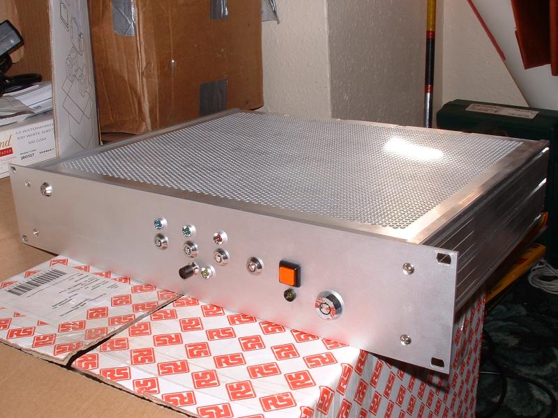
Rack box fully assembled (enlarge)
From Radio Spares, we bought the prototype 2U rack-mountable box, which is a pretty sturdy aluminium case, as well as the following accesories:
| Description | RS Part Number | Cost |
|---|---|---|
| 2 U, 340mm deep case | 259-8969 | £28.44 |
| Closed cover | 259-9057 | £8.24 |
| Perforated cover | 259-9085 | £12.85 |
We bought a Via EPIA ME6000 MINI-ITX motherboard from Mini-ITX.com. This is a fanless motherboard that runs at 600MHz and uses the Via C3 micro-processor. To accompany the board, we also bought a few crucial accessories:
| Description | Cost |
|---|---|
| VIA EPIA ME6000 Motherboard | £89.00 |
| 512MB PC2100 DDR DIMM (Memory) | £89.00 |
| Morex 55W PSU + DC-DC converter | £50 |
| 2 Slot PCI Riser Card | £17.50 |
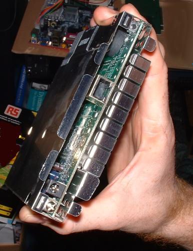
For our box we used a Buffalo Technologies wireless bridge which we had lying around. This simple device has a single RJ45 network connection and acts as a bridge for 802.11b enabled computers. Stripped of its plastic casing, this box is easy to mount in a relatively small space. This device comes with a mains to 7 volt DC adapter with a rating of 1.4 Amps (10 Watts).
| Description | Cost |
|---|---|
| Buffalo wireless bridge | £75.00 |
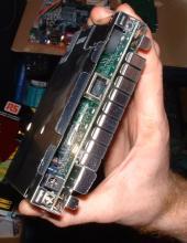
Wireless bridge with plastic cover removed (enlarge)
Note: an alternative wireless access point which we have investigated is the second revision of Apple's Airport, the 802.11b "white" version. The advantage of using this base station is that once the casing is removed and thrown-away, the actual unit is very small and low-profile. However the main bonus is that it runs on 12V, hence there is no need for the construction of a separate regulator circuit to step the voltage down as the battery is 12V as well.
Click here for an article on the Airport, taking it apart and using extended range antennae with it.
To provide uninterruptable power to the device, we purchased a 12 volt 1.2 Amp Hour battery.
To accept mains power and convert it to voltages required to power the devices inside the box, we acquired a variable voltage power supply. An 80 Watt supply would have been necessary without the 12V battery to power the devices on boot, however, with the battery supplying peak currents much higher than a PSU, we decided to go for a 30 Watt power supply to save on space and cooling.
To keep the battery topped up, the voltage was adjusted to 13 Volts.
To power the wireless bridge a small circuit was designed and built from scratch.
A 30GB 2.5 inch hard-drive allows for low noise and power consumption for most applications.
A 80GB 3.5 inch hard-drive was also included for auxiliary storage for use as either direct-to-disk recording of audio and video and is also loaded with a range of compressed music for entertainment purposes. The intention was to have this hard-drive powered on a separate circuit with a switch so that when not required it could be switched off.
Although the motherboard is fanless, with all the extra equipment in this box, and especially the 3.5 inch hard-drive, it was decided to include a fan which can be switched on in high operating temperatures.
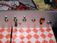
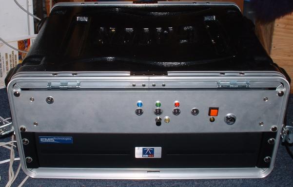
Lights and locking switches on front panel (enlarge)
The front panel serves a number of purposes. Primarily it is there to stop the equipment inside falling out and children from inserting their breakfast into the inner workings. It is also useful for mounting the whole box into a nineteen inch rack. Asides from these important functions, it also must present a set of easy to use controls for switching the equipment on and off and indicating the current status of the equipment inside.
| Description | RS Part Number | Cost | Purpose | |
|---|---|---|---|---|
| 12V Blue LED | 579-893 | £3.51 | Main power | |
| 12V Green LED | 577-128 | £2.26 | WiFi Bridge | |
| 12V Red LED | 577-112 | £2.26 | Motherboard Power Feed | |
| 12V Yellow LED | 577-134 | £2.31 | Fan indicator | |
| 6V Yellow LED | 384-6865 | £3.51 | Motherboard Power indicator | |
| 5 x Radial locking switch | 182-556 | £3.11 each | See below | |
| Pushbutton latching switch | 417-5502 | £4.65 | Fan on/off | |
| Pushbutton switch (red) | 103-6274 | £1.24 | Motherboard on/off | |
| Dual Pole locking switch | Maplins | £2.60 | 3.5 inch hard drive on/off |
The locking switches and LEDs were employed as follows:
Rear Panel (enlarge)
A number of connectors are provided on the rear of the unit by the motherboard:
In addition, the following have been added during the production of the box:
| Description | RS Part Number | Cost |
|---|---|---|
| MCT7806CT 6V Regulator 1.5A Out .. 220 package | 177-5272 | £0.21 |
| 20 degree Celsius per watt heat sink for TO220 | 268-105 | £0.58 x 5 |
| Strip Board | 433-826 | £6.09 |
| 1mm pins | 433-854 | £3.01 |
| Miniature Adhesive Backed Supports | 220-787 | £0.9 x 50 |
| 12V Blue Led in mounting | 579-893 | £3.51 |
| 6V Yellow Led in mounting | 384-6865 | £0.73 x 2 |
We decided not to order the handles :)
Construction took a relatively long time as we didn't exactly know what we'd need and kept having to order extra bits to complete the project. Now that we have a variety of equipment and sundries another similar project would take a much shorter time. An identical project could probably be completed in one working day.
The box was assembled and a sheet of clear insulating material was cut to size to cover the base plate. This is to prevent possible shorting of the motherboard with the case. Double sided sticky tape would be used later to fix this in place, but during production it is useful to leave loose so that holes can be cut in it to allow mounting of devices in the box. As an alternative, sticky-back plastic could be used.
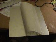
Putting sticky-back plastic on base for insulation (enlarge)
The motherboard was fitted with adhesive backed PCB mounts, giving a support height of 9.5mm for the motherboard. The WiFi bridge was fitted with similar (but smaller) adhesive backed PCB mounts.
| Description | RS Part Number | Cost |
|---|---|---|
| Adhesive backed supports, 9.5mm | 580-001 | £3.50 (per 25) |
| Adhesive backed supports (miniature), 6.5mm | 220-787 | £4.50 (per 50) |
The position of the motherboard and WiFi bridge within the box was then decided so that the rear panel could be marked and cut out to provide access to the ports on the back of the motherboard. Rather than mounting the WiFi bridge flush against the rear panel and cutting another rectangular hole, we decided to 'break out' the RJ45 and reset button separately. The Wifi bridge also needed an arial extension, so a 'pigtail' was used with a round n-type panel mount connector on one end.
| Description | RS Part Number | Cost |
|---|---|---|
| Tool-free female RJ45 panel mount connector | 365-6384 | £4.00 |
| Pushbutton switch, panel mount (round) | 103-6274 | £1.24 |
| Pigtail connector | MicroWareHouse | £24.00 |
Once the PCI riser card was connected to the motherboard and the cardbus to PCI converter was attached, we realised that the WiFi bridge would fit nicely underneath the riser, giving us plenty or room for the other devices in the box. The only problem that we envisaged, would be when a WiFi card was used in the cardbus slot and the card would be very close to the WiFi bridge and hence they would interfere with each other. Using separate channels when working with different networks would minimise this problem as well as the fact that extended range antenna would be attached to the rear panel further separating the signals.

Components placed to allow marking of positions prior to cutting (enlarge)
One issue that is well worth checking is that when the motherboard is mounted flush with the rear panel, the fixing screws that are used to attach the base place of the rack box to the rear panel are long enough to interfere with some of the longer-footed surface mount devices on the motherboard. We measured the distances involved using vernier callipers and decided that the screws supplied with the rack case were too long for comfort and we replaced them with shorter screws where necessary.
Now that we knew exactly where we wanted everything to be, we marked the positions on the rear panel and base plate, disassembled the rack box and got drilling and cutting. Much measuring and care must be taken when cutting the rear panel, followed by more measuring and careful filing down to give everything a perfect fit and finish. We actually found this to be very very difficult indeed, and none of the square holes we cut ended up looking very neat on close inspection.
Tip: Cover the aluminium of the rack box with masking tape so that it can be easily marked and is not scratched by the jigsaw or files.
We replaced the adhesive backed PCB mounts with threaded hexagonal PCB mounts cut to length to provide more robust mounts on the motherboard PCB nearest the rear panel.
The 12V DC-DC converting power supply that came with the motherboard mounted nicely on it's side up against one side of the rack box. The rack box is actually slotted to take slot-mounted mounting nuts, but we used adhesive backed PCB mounts because we had them at hand, and the power supply was well supported by the cable bundle leading to the motherboard. Extra holes were drilled in the PCB to allow an extra two mounts to provide more stability.

Motherboard and power supply unit (enlarge)
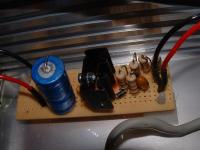
Regulator circuit (enlarge)
The 12 volt to 7 volt converter was built using the LM317T integrated circuit chip and some assorted components listed here. I am absolutely sure that I've over-specified the auxiliary components, such as diodes and resistors, but we are not particularly pushed for space, and larger components are easier to work with.
| Description | RS Part Number | Cost |
|---|---|---|
| PCB Strip board (Veroboard) | 433-826 | £6.24 |
| IC, voltage regulator, adj, positive, LM317T | 370-3910 | £2.32 each |
| Heat sink, T0220, 23degC/W | 268-105 | £0.35 each |
| Capacitor 25Vdc 2200uF | 324-5212 | £0.93 each |
| Capacitor 35Vdc, 0.1uF | 221-8584 | £0.13 each |
| Capacitor 35V, 1uF | 262-5027 | £0.23 each |
| Diode, Rectifier, 1N4002 | 261-154 | £0.05 each |
| 2 x Resistor, 0.5W, 5%, 100R | 132-258 | £0.04 each |
| PCB terminal pins | 433-854 | £3.09 for 500 |
Regulator Circuit Diagram
Don't be fooled by the circuit diagram - check the pin outs on the data sheet for the regulator IC, the circuit diagram is laid out to make it easy to follow, not to give you an actual design on the vera board. Use heat transfer compound to attach the heat sink to the regulator chip. Use the PCB terminal pins to give you power in and out, preparing the copper strip with some solder before inserting the pin, and then pressing down on the base of the pin with the soldering iron to solder the pin to the strip. The pins can then be soldered to the wires taking power to and from the regulator circuit. Drill some 4mm holes in the vera and use the adhesive backed PCB mounts to fix the circuit into the box.

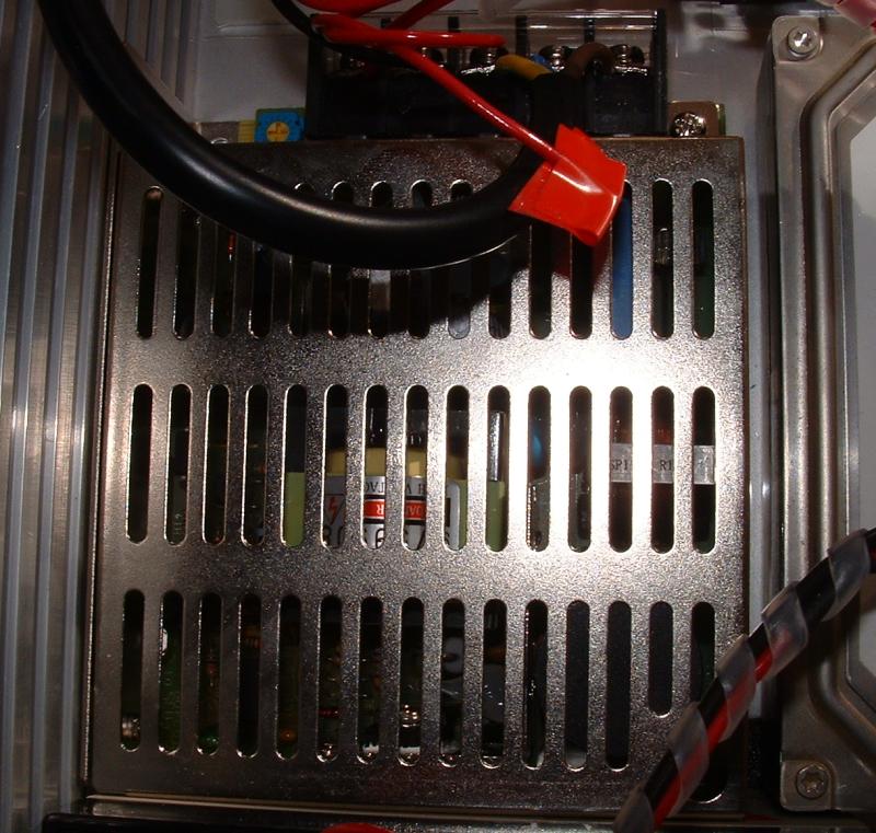
Main power supply unit (enlarge)
The power supply was chosen for it's wide universal AC input and it's adjustable output that will take it up to 13.9 volts (great for float charging batteries). The power supply was firmly fixed using screws through the base of the rack box.
| Description | RS Part Number | Cost |
|---|---|---|
| PSU, universal AC I/P, 110Vac, 230VAC, adj O/P 12V, 3A, 35W | 418-2184 | £29.58 |
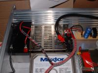
Battery and power supply units mounted in box (enlarge)
The battery was mounted very close to the power supply unit, secured with double-sided cushioned sticky tape. A Yuasa 12 volt 1.2 Amp Hour battery was used. This was wired direct to the main power supply, with a cutoff switch to prevent the small current leakage back into the power supply when the unit is not in use. The adjustment of the power supply to 13 volts provides a nice float charge to keep the battery topped up. When the battery reaches 13 volts, there is no longer any potential difference between the power supply and the battery, so no further current flows. Diodes where not used to prevent current leakage as these bring in a 0.7 volts drop in voltage, which we didn't want to contend with.
The 2.5 inch hard drive was mounted on it's side, with cushioned double-sided sticky tape to provide some cushioning between the disc drive and the base of the rack box. More tape was used to provide lateral strain relief between the disc drive and side of the rack box.
The 3.5 inch disc drive was mounted horizontally, using hexagonal PCB mounts 10mm long
All switches and LEDs where round panel mount types, making it much easier and quicker to construct. Although each individual switch was simple to wire up, the number of switches and LEDs made it quite a jumble of wires, so care was taken when routing the wires to make things as tidy as possible.
All wires were soldered rather than connected using connectors and loads of heat-shrink tubing was used to minimise the possibility of shorts.
Transport to and from events is the time when the most damage can be done to equipment. By the time a gig is complete, the last thing you want to do is spend time making sure the equipment is handled with due care and attention. The sky is the limit when buying protective cases for equipment. As this is a prototype machine, we thought we'd plump for an off the shelf hard case without any special shock-mounts. Once the box has proved its robustness in this environment and we have completed the prototyping phase, we'll be kind to it and get a fully shock-mounted box to carry it around in.

Completed unit installed in rack case (enlarge)
Make sure that the rack case is going to be deep enough for the 2U rack unit you are going to put in it; a lot of the audio cases are not very deep at all because of the relatively small size of music equipment!
We went for a Gator Cases standard 4U rack case. These have 496mm of rack-able depth to them (19.5 inches). Purchased from http://www.proaudiosystems.co.uk At a price of £57 + VAT.
Author: Iain Kennedy
Copyright (c) 2003, 2004 Psand Limited. Permission is granted to copy, distributed and/or modify this document under the terms of the GNU Free Documentation License, Version 1.1 or any later version published by the Free Software Foundation; with no Invariant Sections, with no Front-Cover Texts, and with no Back-Cover Texts. A copy of the license is included in the section entitled "GNU Free Documentation License".
All trademarks are those of their respective trademark holders.