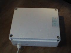
The waterproof box sealed and ready for use.
Updated 12 December 2005 (2005-12-12)
An easy way to improve the coverage of a wireless access point outdoors is to raise the antenna above nearby obstacles. This gives a much better line of sight. The downside to this is that the longer the cable run between the wireless device and the antenna the greater the signal loss. Buying increasingly expensive microwave transmission cable, with less signal loss per metre, can help but there is a cutoff point over a certain length (likely to be upwards of 20 metres) at which the useable signal is lost completely.
This page attempts to cover another solution, which though no less expensive is considerably more flexible.
The solution involves using power over ethernet, and a waterproof box to enable the wireless device to be mounted up high (up to 100 metres away). Power over Ethernet allows the network signal and the power to be transmitted along the same CAT5 ethernet cable. CAT5 cable is much cheaper than nice microwave transmission cable, and allows much longer cable runs without the radio signal losses.
The waterproof box sealed and ready for use.
The theory and practise behind this is very simple and may seem obvious to those used to working with the equipment, however, for the benefit of those who are struggling with line of sight / coverage, these details could be very useful.
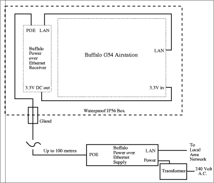
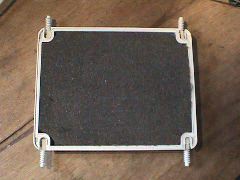
Schematic showing connection of Airstation, POE supply and receiver,
and the containment within the waterproof box.
The IP68 polyamide gland (IP ratings list, IP ratings explained) required a 15mm hole in the waterproof box. This was drilled in what would be the bottom of the box. It should not matter where the connector is on the box because it is very well specified for waterproofing. The hole was drilled with a cone cutter, and the polyamide gland was fitted tightly.
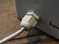
The gland viewed from outside the box.
Next was added the long ethernet cable to carry the network signal and power from our network to the Airstation. Due to the small aperture in the Polyamide gland, it was nescessary to fit RJ45 connectors to the ethernet cable after passing the cable through it. This required the use of an RJ45 crimp tool, but I am sure that most computer shop / service centres would have one, and could do this bit, if you have no crimp tool. It is a good idea to ensure that this cable is adequately long because it will require re-making to make it longer or shorter.
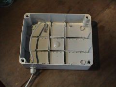
Long ethernet cable made into the box.
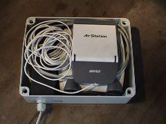
The Airstation was placed in the box, along with the Power over Ethernet receiver.
The box end of the long ethernet cable was connected to the Power over Ethernet receiver POE socket, and the gland was tightened securely to ensure it was waterproof.
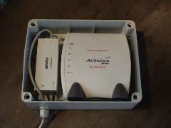
The Airstation and POE receiver in the box, with long ethernet cable connected.
A short ethernet cable was supplied with the Power over Ethernet equipment, and this was used to connect the Power over Ethernet receiver LAN connection to the Airstation's LAN port. The power output of the Power over Ethernet supply (3.3 Volts DC) was connected to the DC input on the Airstation.
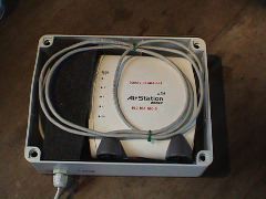
The cables inside the box were laid in as neatly and carefully as possible, to ensure they did not get trapped.
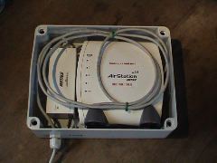
The hardware connected up.
The other end of the long ethernet cable was then connected to the POE socket on a Buffalo Power over Ethernet supply unit, and the Power over Ethernet supply unit was powered up. This was done before the lid was put on the box, to check everything was working fine.
The Power over Ethernet supply connected and powered up.
Once all the lights came on and the Airstation was happy, small pieces of foam were cut to hold the hardware firmly in position in the box. Once well packed the lid was screwed down tightly onto the box, ensuring that the seals were in place and no cables were trapped.
The foam in place ready for the lid.
The inside of the box lid, showing foam padding.
Next our network was connected to the LAN socket on the Power over Ethernet unit and the Airstation configured. It is beyond the scope of this document to explain the configuration - refer to the manual.
It would have been possible to remove the Airstation and Power over Ethernet receiver at this point, leaving only the long ethernet cable attached, put the lid back on the box and submerge it in a bowl of water overnight to confirm that the Polyamide gland had been fitted correctly, but this was not done, and our Airstation has not yet got wet.
As of yet no clever mounting has been devised which maintains the waterproof nature of the box, as it is not possible to drill into the box. So far we have used a luggage strap (like a small ratchet strap) to mount it onto a pole. Care was taken not to allow the metal fastener to obscure the signal from areas in which it was needed.
On reflection it would make more sense to put the gland on the side of the box, because then the box would sit on a flat surface (like a windowsill or the roof of a vehicle) more easily.
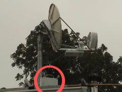
The box in use (in the rain) on the roof of our vehicle, sharing out the broadband connection from the satellite dish behind. This setup is at the Big Green Gathering 2003, and is solar / wind powered.
Thought needs to be applied to the polarisation of the antenna within the Airstation and hence the polarisation of the box when mounting. The Airstation is designed to stand upright, although the PCMCIA card within the Airstation is actually on its side, and the PCMCIA antennas do not have good coverage anyway.
There is room in the waterproof box to fit a Buffalo extended range antenna lying flat on top of the Airstation. This enables the forward gain of the box to be increased by around 4dB, and the antenna has a beamwidth of around 75 degrees. As more coverage is now available from the front of the box, the direction of the mounting becomes more important, and if the box is to mounted up high, then it may need a small amount of down-tilt, otherwise the signal may be lost over the heads of those needing the signal. This setup roughly doubles the range of the coverage in the forward direction.
The extended range (sector) antenna in place.
The repeated and heavy use of the term Buffalo in this document does not constitute an endorsement of Buffalo products, Buffalo themselves, the Royal Antediluvian Order of Buffaloes, the Colorado Buffaloes football team etc. etc.....
Everything you do, you do at your own risk.
Wireless device manufaturers say you should not do anything they say you should not do, of course.
Author: Dave Gough
Copyright (c) 2003-2004 Psand Limited. Permission is granted to copy, distributed and/or modify this document under the terms of the GNU Free Documentation License, Version 1.1 or any later version published by the Free Software Foundation; with no Invariant Sections, with no Front-Cover Texts, and with no Back-Cover Texts. A copy of the license is included in the section entitled "GNU Free Documentation License".