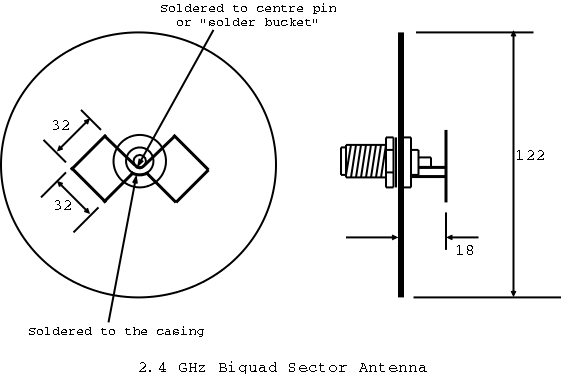
A semi-technical diagram of the biquad antenna
Note - This antenna is for use with 802.11b wireless computer networks or 2.4GHz video sending equipment. It is not for FM / AM / SW / LW radio useage.
Latest version of this document | More articles
This sector antenna was made from a piece of thick copper wire formed into a "bowtie" shape (the biquad - with sides 32 millimetres) and soldered to a round N-type connector. The N connector was then screwed into a steel disc about the size of a CD (Compact Disc).
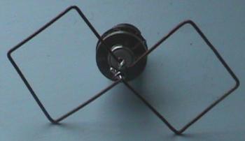
The original prototype (shown) is still in use two years later, and has survived severe storms.
A semi-technical diagram of the biquad antenna | Note - This antenna is for use with 802.11b wireless computer networks or 2.4GHz video sending equipment. It is not for FM / AM / SW / LW radio useage. |
N-type socket round "through bulkhead" came from R.S. number 112-0773. Packaging says Telegartner (Manufacturer presumably) Type N-Einbaubuchse J01021A1084 Tel +49 (0) 7157/125-0 Fax -120
The "bowtie" section was made from a length of copper at least 400 mm (0.4 metre) long. The wire came from standard twin-and-earth stiff household mains wiring. By holding either end of the wire with a pair of pliers and giving it a sharp tug the wire was straightened. Leaving about 20 mm before starting, the bowtie shape was folded into the wire using the pliers, with the side of each square being 32 mm. The edge of the pliers was useful to obtain right angles. Both ends of the wire end up in the same place once the "bowtie" is formed. These were soldered together and bent 90 degrees out of the plane of the bowtie, ready to be soldered to the casing of the N-type connector. The "bowtie" then had an extending piece of wire soldered to it at the point where there is a 90 degree bend joining the two squares together, ready to be soldered to the centre pin (solder bucket) of the N-type connector.
We worked out where the rear disc (groundplane) would sit when the N-type connector was affixed to it, and then both extending wires we cut so as to stand the "bowtie" off the back plate by 18 mm. The centre pin was easy to solder because it has been tinned by the manufacturer. Soldering the other extending wire to the casing was not so easy. It required the surface roughing with sandpaper, and then tinning with a lot of heat until the solder flows. Once the casing and the end of the wire extension was tinned soldering was easy, while the connector body was still hot. At this point the dialectric (the white bit around the centre pin) started to go a bit soft. We were careful not to move the pin, and ensure it was straight before it cooled.
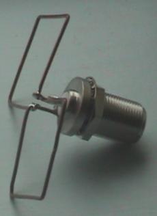
The "bowtie" and N-type connector assembly, before fitting to the ground plane.
We drew around a compact disc on to a sheet of galvanised steel (about 1 mm thick - but none of use know our steel gauges - think it's 8 gauge) - and marked the centre. We used a pair of tin snips to cut out the circle. Using a 20 mm cone cutter, we drilled a 16 mm hole on the centre of the disc (by putting the 16 mm washer from the N-type connector over the tip of the cutter before drilling the hole stops at exactly the right size. We de-burred the edges of the disc with a fine file.
We screwed the "bowtie" and connector assembly into the hole in the ground plane, tightened it up with two spanners, and then carefully adjusted the "bowtie" wire until the plane of the "bowtie" was nicely parallel to the ground plane.
We have used no weather proofing on these antennas yet. It needs some kind of plastic cap over the front.
The antenna mounted on the U-bolt assembly.
These antennas need aiming. We mounted the antenna on a u bolt assembly using the bottom two bolts only. Thus we drilled two holes in the ground plane at the top. Ensuring the bolts protruded only a nut width, and using 2 nuts behind and 2 nuts in front, secured the ground plane to the lower u-bolt
The U-bolt assembly was clamped down hard on the bar, pointing in the required direction.
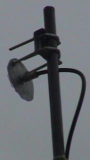
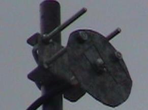
The antenna mounted on the pole, showing cable tie at the bottom as strain relief for the cable.
£5.50 for the N connector. The wire and steel disk were recycled. The u-bolt mounting assembly was around £3.00
Apart from the fact it works really well, no-one has yet popped on their lab-coat and done any high-brow tests on this "homebrew twig", and of course manufacturers recommend you don't do anything which they don't recommend, or attach non-proprietary stuff to their stuff. Of course.
Initial tests show that the antenna has a beamwidth of roughly 70 degrees in elevation (vertical) and azimuth (horizontal) planes, and 12 dB gain in the signal to noise ration over the pcmcia card.
Author: Dave Gough
Copyright (c) 2002 Psand Limited. Permission is granted to copy, distributed and/or modify this document under the terms of the GNU Free Documentation License, Version 1.1 or any later version published by the Free Software Foundation; with no Invariant Sections, with no Front-Cover Texts, and with no Back-Cover Texts. A copy of the license is included in the section entitled "GNU Free Documentation License".